|
Peter,
Please find attached your photos with
comments.
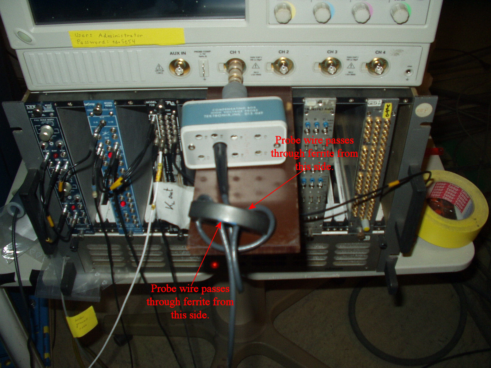
1) Scope.jpg: it is not clear to me whether the probe
cable passes through the ferrite 2 or 3 times. However 2 of the times are in
opposite directions (I believe) and therefore these turns will cancel
magnetically: the cable must always go through the ferrite from the same
side.
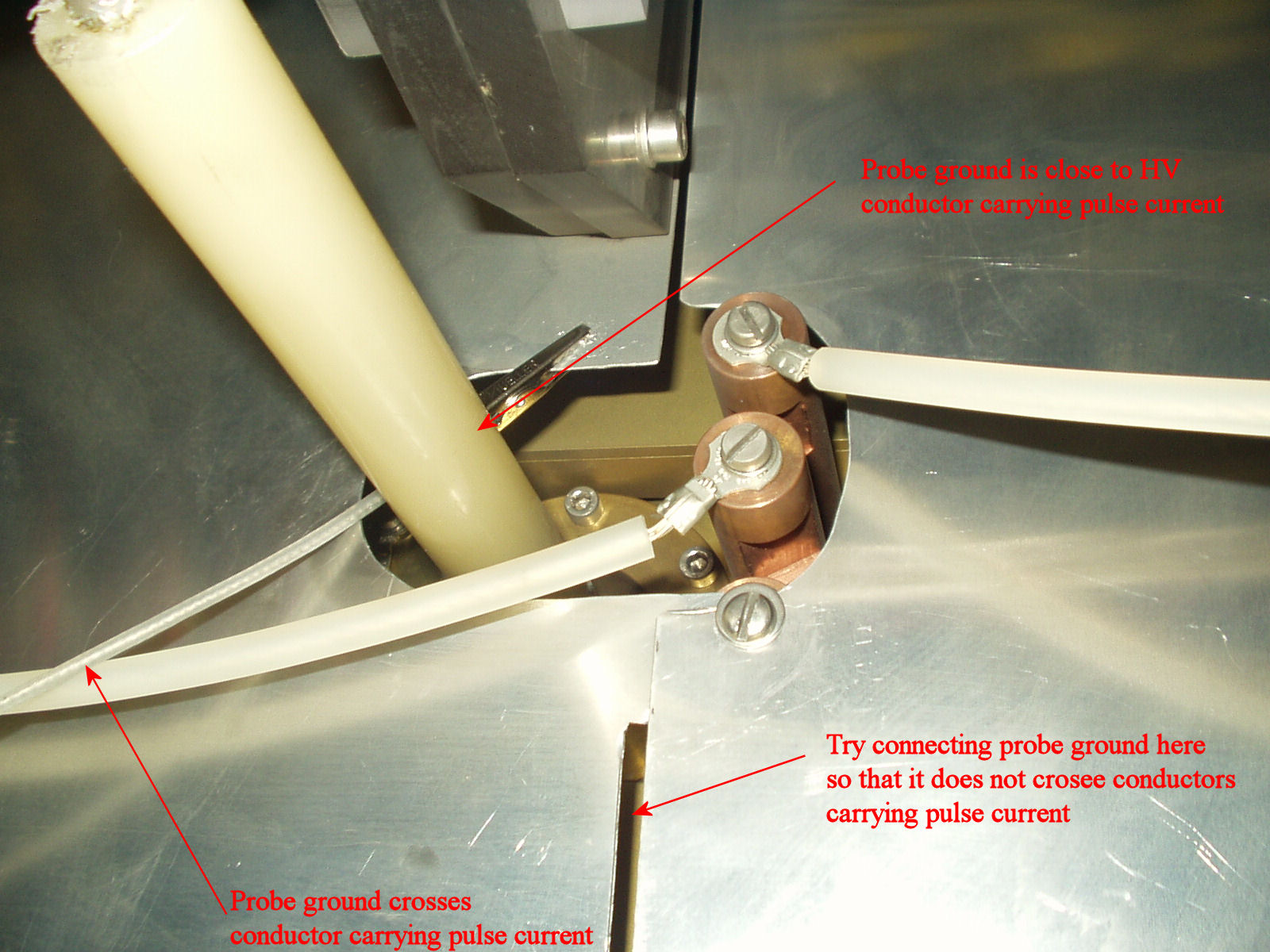
2) Ground.jpg: the ground wire from the probe goes
close to both the conductor carrying return current from the stack as well as
the HV conductor. Please arrange for the probe ground wire to be reasonable
distant from conductors carrying pulse current (while still attaching near to
the central ground).
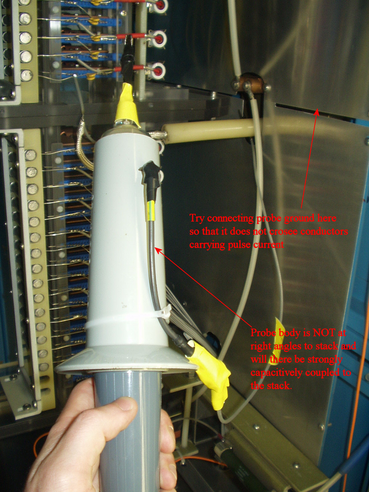
3) probe.jpg: the probe, as shown, will be strongly
capacitively coupled to the stack and will therefore pick up a lot of noise.
Please hold the probe at right angles to the stack.
Others
=====
A) When you measure the voltage of a card, are you
ensuring that the probe is DIRECTLY touching either the drain or source
connection of the card of interest? (the probe should not be at the other end of
the short wire that connects different cards, as this wire carries pulse
current).
B) As per Francoise's suggestion, it would be a good
idea to average a measurement, e.g. 25 times, to reduce background
noise.
C) Please confirm your numbering system: is "1" at the
DC or pulse end of the stack? (we consider "1" to be the DC
end).
D) As far as reasonably possible keep the probe ground
wire close to the side of the cabinet, as this will minimize induced
currents.
Cheers,
Mike From: Peter Winter [mailto:peter.winter@psi.ch] Sent: Wednesday, May 03, 2006 2:28 AM To: Peter Winter Cc: Mike Barnes; Mulhauser Francoise; kiburg@npl.uiuc.edu; kammel@npl.uiuc.edu Subject: Re: Kicker grading measurement I put together some pictures. The following two pictures (which have to be rotated by +90 and -90 degree, respectively) showour ground cable for the HV probe connected inside the cabinet. The length is around 30-40cm. And that's the HV cable connected to the oscilloscope: Finally, here's how we measure: Since we are expecting beam tomorrow, we prepared the kicker to be in kicking mode. During the next beam off time, we'll continue the measurements, repeat the series for one card and see how it changes (although we already did that and the results are quite stable). Greetings Peter |
Attachment:
scope.jpg
Description: scope.jpg
Attachment:
ground.jpg
Description: ground.jpg
Attachment:
probe.jpg
Description: probe.jpg